Description
This is a simple touch dimmer circuit made of IC TT6061 . TT 6061 is specifically designed for this purpose.By touching this touch dimmer you can increase the light intensity of incandescent lamps in three steps
At first, when mains is ‘on,’ the lamp is ‘off’. When you touch the plate, the lamp glows dimly. At second touch, the bulb gives medium light. On the third touch, the bulb is driven fully.Next touch puts off the light off.
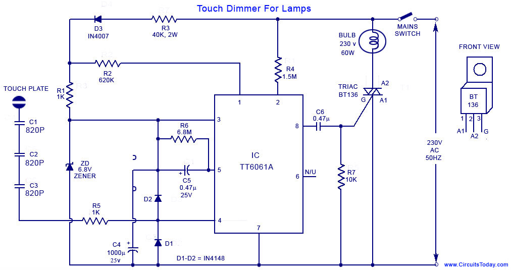
Line frequency is taken through R4 to pin 2 of IC.At zero crossing the IC fires a pulse to trigger the triac.The width of this firing pulse depend on the n0: of touches on the plate.Thus by each touch the firing angle of SCR is varied which in turn varies the brightness of lamp.
Components R1, R3, D3, ZD, and C4 form the power supply section. Resistors R1 and R3 limits the inrush current. Diode D3 is used for rectification while Zener diode ZD does the job of rectification. C4 is the filter capacitor. Pin 1 and 2 of the system frequency input pin and input frequency input pin respectively. Pin2 is connected to the mains voltage using a 1.5K resistor and pin 1 is connected to the cathode of the rectifier diode using a 620K resistor. R7 is the pull down resistor for the gate of the TRIAC.Capacitors C1, C2 and C3 are meant for isolation. Never change their value or replace them with a single one.For the touch plate we can use a 1 square cm metal plate.
Caution!
Use exact rating capacitors with the touch plate. Do not touch any other part of circuit other than touch plate.Ensure that the touch plate is not live, using a tester before using or testing the circuit.Do not use a bulb with power rating more than 200 Watts. Do this circuit under your own risk.I have no responsibility for any mishaps.
Pin Assignments of IC TT6061A.
Pin No. Pin name Function description
1 CK System clock input
2 FI 50Hz line frequency
3 VDD Power input pin for VDD
4 TI Touch input
5 CI Sensor control input
6 NC Not connected
7 VSS Power input pin for VSS
8 AT
Touch Dimmer Circuit Diagram .

This is a simple touch dimmer circuit made of IC TT6061 . TT 6061 is specifically designed for this purpose.By touching this touch dimmer you can increase the light intensity of incandescent lamps in three steps
At first, when mains is ‘on,’ the lamp is ‘off’. When you touch the plate, the lamp glows dimly. At second touch, the bulb gives medium light. On the third touch, the bulb is driven fully.Next touch puts off the light off.
Line frequency is taken through R4 to pin 2 of IC.At zero crossing the IC fires a pulse to trigger the triac.The width of this firing pulse depend on the n0: of touches on the plate.Thus by each touch the firing angle of SCR is varied which in turn varies the brightness of lamp.
Components R1, R3, D3, ZD, and C4 form the power supply section. Resistors R1 and R3 limits the inrush current. Diode D3 is used for rectification while Zener diode ZD does the job of rectification. C4 is the filter capacitor. Pin 1 and 2 of the system frequency input pin and input frequency input pin respectively. Pin2 is connected to the mains voltage using a 1.5K resistor and pin 1 is connected to the cathode of the rectifier diode using a 620K resistor. R7 is the pull down resistor for the gate of the TRIAC.Capacitors C1, C2 and C3 are meant for isolation. Never change their value or replace them with a single one.For the touch plate we can use a 1 square cm metal plate.
Caution!
Use exact rating capacitors with the touch plate. Do not touch any other part of circuit other than touch plate.Ensure that the touch plate is not live, using a tester before using or testing the circuit.Do not use a bulb with power rating more than 200 Watts. Do this circuit under your own risk.I have no responsibility for any mishaps.
Pin Assignments of IC TT6061A.
Pin No. Pin name Function description
1 CK System clock input
2 FI 50Hz line frequency
3 VDD Power input pin for VDD
4 TI Touch input
5 CI Sensor control input
6 NC Not connected
7 VSS Power input pin for VSS
8 AT
Touch Dimmer Circuit Diagram .